


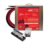


The EVO™ Inverter/Charger series is able to support charging LiFePO4 batteries. The following items are a quick setup list of parameters that need to be changed from defaults on your EVO-RC or EVO-RC-PLUS remote to get your system up and running with the correct charge profile for Lithium-Ion (LiFEPO4) batteries.
The following settings are provided assuming the following:
- LiFePO4 Battery includes an internal Battery Management System (BMS)
- Has a nominal voltage of 12.8 VDC
- EVO™ Inverter Charger default settings are assumed to be programmed
The charge voltage settings are recommended based on typical manufacturer specifications. Reference your battery manufacturer’s settings where indicated and adjust accordingly.
The charge profile, low voltage alarm, and shutdown settings are user preference. Recommendations are provided based on typical operation and can be changed to suit your specific use as you become familiar with your system’s limits.
EVO™ Parameter | Setting | Notes |
|---|---|---|
Charging Profile | 1 = 3 Stage Type 1 | Samlex recommendation |
Absorption Voltage | 14.4 V | Set this based on your battery manufacturer’s recommendation. |
Float Voltage | 13.5 V | Set based on manufacturer’s recommendation. If there isn’t a recommended setting, contact your manufacturer. |
Reset To Bulk | 13.0 V | Samlex recommendation. |
Absorb Time | 60 mins | Set this based on your battery manufacturer’s recommendation. |
Battery Type | Lithium | Samlex recommendation. |
Low Voltage Alarm | 12.0 V | Buzzer will sound at this voltage. This is a user preference setting and a warning that the batteries are discharged. |
Battery Low Voltage | 11.0 V | EVO™ inverter will shutdown below 11.0v – user preference |
LV Cut Off Time | 300 seconds | Battery low voltage shutdown occurs 300 seconds after voltage detected – user preference. |
Reset Voltage | 13.2 V | After Battery Low Voltage has been initiated, the battery will need to be charged to this voltage before the inverter will restart. |
If you have further questions regarding these settings or other elements within your system, please feel free to contact us at Samlex America 1-800-561-5885.
You can also download this Application Note.
Lithium-Ion Battery Setup for EVO™ Inverter / Chargers
The output voltage of a sine-wave inverter has a sine wave-form like the sine wave-form of the mains / utility voltage. In a sine wave, the voltage rises and falls smoothly with a smoothly changing phase angle and also changes its polarity instantly when it crosses 0 Volts. In a modified sine wave, the voltage rises and falls abruptly, the phase angle also changes abruptly and it sits at 0 Volts for some time before changing its polarity. Thus, any device that uses a control circuitry that senses the phase (for voltage / speed control) or instantaneous zero voltage crossing (for timing control) will not work properly from a voltage that has a modified sine wave-form.
Also, as the modified sine wave is a form of square wave, it is comprised of multiple sine waves of odd harmonics (multiples) of the fundamental frequency of the modified sine wave. For example, a 60 Hz. modified sine wave will consist of sine waves with odd harmonic frequencies of 3rd (180 Hz), 5th (300 Hz.), 7th (420 Hz.) and so on. The high frequency harmonic content in a modified sine wave produces enhanced radio interference, higher heating effect in motors / microwaves and produces overloading due to lowering of the impedance of low frequency filter capacitors / power factor improvement capacitors.
Advantages of sine-wave inverters
- The output wave-form is a sine-wave with very low harmonic distortion and clean power like utility supplied electricity
- Inductive loads like microwaves and motors run faster, quieter and cooler
- Reduces audible and electrical noise in fans, fluorescent lights, audio amplifiers, TV, fax and answering machines
- Prevents crashes in computers, weird print outs and glitches in monitors
Some examples of devices that may not work properly with modified sine wave and may also get damaged are given below:- Laser printers, photocopiers, magneto-optical hard drives
- The built-in clocks in devices such as clock radios, alarm clocks, coffee makers, bread-makers, VCR, microwave ovens etc may not keep time correctly
- Output voltage control devices like dimmers, ceiling fan / motor speed control may not work properly (dimming / speed control may not function)
- Sewing machines with speed / microprocessor control
- Transformer-less capacitive input powered devices like (i) Razors, flashlights, night-lights, smoke detectors etc (ii) Re-chargers for battery packs used in hand power tools. These may get damaged. Please check with the manufacturer of these types of devices for suitability
- Devices that use radio frequency signals carried by the AC distribution wiring
- Some new furnaces with microprocessor control / Oil burner primary controls
- High intensity discharge (HID) lamps like Metal Halide lamps. These may get damaged. Please check with the manufacturer of these types of devices for suitability
- Some fluorescent lamps / light fixtures that have power factor correction capacitors. The inverter may shut down indicating overload
You can also download this Application Note.
Inverters – Advantages of Pure Sine Wave Inverters
Conductors for electrical power distribution
For single phase transmission of AC power or DC power, two conductors are required that will be carrying the current. These are called the “current-carrying” conductors. A third conductor is used for grounding to prevent the build up of voltages that may result in undue hazards to the connected equipment or persons. This is called the “non current-carrying” conductor (will carry current only under ground fault conditions)
Grounding terminology
The term “grounded” indicates that one or more parts of the electrical system are connected to earth, which is considered to have zero voltage or potential. In some areas, the term “earthing” is used instead of grounding.
A “grounded conductor” is a “current-carrying” conductor that normally carries current and is also connected to earth. Examples are the “neutral” conductor in AC wiring and the negative conductor in many DC systems. A “grounded system” is a system in which one of the current-carrying conductors is grounded.
An “equipment grounding conductor” is a conductor that does not normally carry current (except under fault conditions) and is also connected to earth. It is used to connect the exposed metal surfaces of electrical equipment together and then to ground. Examples are the bare copper conductor in non-metallic sheathed cable (Romex®) and the green, insulated conductor in power cords in portable equipment. These equipment-grounding conductors help to prevent electric shock and allow over-current devices to operate properly when ground faults occur. The size of this conductor should be coordinated with the size of the over-current devices involved
A “grounding electrode” is the metallic device that is used to make actual contact with the earth. Other types of grounding electrodes include metal water pipes and metal building frames.
A “grounding electrode conductor” is the conductor between a common single grounding point in the system and the grounding electrode
“Bond” refers to the connection between the “grounded conductor”, the “equipment grounding” conductors and the “grounding electrode” conductor. Bonding is also used to describe connecting all of the exposed metal surfaces together to complete the equipment-grounding conductors.
Grounded Electrical Power Distribution System
The National Electrical Code (NEC) requires the use of a “grounded electrical distribution system” for a permanently connected AC power source. As per this system, one of the two current-carrying conductors is required to be grounded. This grounded conductor is called the “Neutral / Cold / Return”. As this conductor is bonded to earth ground, it will be at near zero voltage or potential. There is no risk of electrical shock if this conductor is touched. The other current carrying conductor is called the “Line / Live / Hot”. The connection between the “Neutral” and the grounding electrode conductor is made only at one point in the system. This is known as the system ground. This single point connection (bond) is usually made in the service entrance or in the load center. If this connection is inadvertently made in more than one place, then unwanted currents will flow in the equipment grounding conductors. These unwanted currents may cause inverters and charge controllers to be unreliable and may interfere with the operation of ground-fault detectors and over-current devices
NOTE: In a single phase AC power source, a current-carrying conductor that is not bonded to the earth ground cannot be called a “neutral”. This conductor will be at an elevated voltage with respect to the earth ground and may produce electrical shock when touched.
Polarity and color codes for power cords, plugs and receptacles for AC devices and appliances
Single phase 120 VAC, 60 Hz AC devices and appliances use 2 pole, 3 wire grounding configuration for making AC side connections. The plug / receptacle has three pins / slots – two flat pins / slots (also called poles) that are connected to the two current-carrying conductors and a round pin / slot which is connected to a non-current carrying conductor (this will carry current only during ground fault conditions) One flat pin / slot is connected to a black current-carrying conductor which is also called “Line/Live/Hot” pole. The other flat pin / slot is connected to the white current-carrying conductor also called the “Neutral / Return / Cold” pole. The third round pin / slot is connected to the non-current carrying green “equipment grounding conductor”. This green “equipment grounding conductor” is bonded to the metal chassis of the device or appliance. The plug (for example 15 A, NEMA5-15P) will mate with the corresponding female slots of the NEMA 5-15R receptacle
Inverters where one of the current carrying conductors is not bonded to the chassis
In some inverters designed for portable use, the two current carrying conductors connected to the “Line/Live/Hot” slot and the “Neutral / Return / Cold” slot of the receptacle ( for example, 15 A NEMA5-15R) are isolated from the metal chassis of the inverter. In these inverters, none of the two poles can be called Neutral as both these poles are isolated from the chassis of the inverter. Both the Line and Neutral slots of the receptacle will be at an elevated voltage with respect to the chassis – normally around 60 VAC (Half of the voltage between the two current carrying conductors). Hence, do not touch the neutral slot of the receptacle!
These types of inverters are designed to be connected directly to the AC loads. These are not designed to be permanently installed into household or recreational vehicle AC distribution wiring. As this type of connection / installation can not be classified as a permanent installation, the NEC requirement of grounded distribution system doesn’t strictly apply. The UL standard for this type of inverters- UL458 does not have a requirement for a bonded neutral on the output of inverters. As long as the installation requirement of grounding the chassis of the inverter has been accomplished, loads that are plugged in will have their chassis held at the same ground potential as the chassis of the inverter and the house or RV. The only difference is that the neutral slot of the receptacle has approximately 60V on it instead of the usual 0V. The impact of this is minimal, since parts of wiring and equipment that are connected to the neutral side of the circuit are required by safety standards to be treated as if they were at 120VAC, since there are many receptacles that are wired backwards or 2-prong plugs that are not polarized. Therefore, a voltage of approximately 60VAC of the Neutral slot is not accessible to the user, and any shock hazard presented is mitigated by lack of access. The main safety agencies, CSA, UL, and ETL, have all approved inverters with this half-voltage on the neutral scheme.
You can also download this Application Note.
Inverters – Grounding and Neutral Bonding
The inverter contains internal switching devices which generate conducted and radiated electromagnetic interference (EMI).
The magnitude of EMI is limited to acceptable levels by circuit design but can not be entirely eliminated. The effects of EMI will also depend upon a number of factors external to the power supply like proximity of the inverter to the EMI receptors, types and quality of connecting wires and cables etc. EMI due to factors external to the inverter can be reduced as follows:
- Ensure that the inverter is firmly grounded to the ground system of the building or the vehicle
- Locate the inverter as far away from the EMI receptors like radio, audio and video devices as possible
- Keep the DC side cables between the battery and the inverter as short as possible
- Twist the DC side cables. This will partially cancel out the radiated noise from the cables
- Shield the DC side cables with metal sheathing / copper foil / braiding
- Use co-axial shielded cable for all antenna inputs (instead of 300 ohm twin leads)
- Use high quality shielded cables to attach audio and video devices to one another
- Do not operate other high power loads when operating audio / video equipment
You can also download this Application Note.
Inverters – Limiting Electromagnetic Interference
The inverter will require Deep Cycle Lead Acid Batteries of appropriate capacity
Lead-acid batteries can be categorized by the type of application: automotive service – Starting/Lighting/Ignition (SLI, a.k.a. cranking) and deep cycle service
SLI Batteries
Everybody is familiar with the SLI batteries that are used for automotive starting and powering vehicular accessories. SLI batteries are designed to produce high power in short bursts but must be constantly recharged (normally with an alternator while driving). Vehicle starting typically discharges 1%-3% of a healthy SLI battery’s capacity.
The automotive SLI battery is not designed for repeated deep discharge where up to 80% of the battery capacity is discharged and then recharged. If an SLI battery is used for this type of application, its useful service life will be drastically reduced.
Deep Cycle Batteries
Deep cycle batteries are designed with thick-plate electrodes to serve as primary power sources, to have a constant discharge rate, to have the capability to be deeply discharged up to 80 % capacity and to repeatedly accept recharging. They are marketed for use in recreation vehicles (RV), boats and electric golf carts – so they may be referred to as RV batteries, marine batteries or golf cart batteries. There are two categories of deep cycle lead acid batteries – wet and sealed. A wet cell battery has a high tolerance to overcharging. However, it will release hydrogen gas when charging that must be properly vented and the water level must be checked frequently. Sealed batteries can either be Gel Cell or AGM (Absorbed Glass Mat). Both the Gel Cell and AGM are maintenance free, have no liquid to spill and gassing is minimal. The Gel Cell is the least affected by temperature extremes, storage at low state of charge and has a low rate of self discharge. An AGM battery will handle overcharging slightly better than the Gel Cell.
Units of Battery capacity
The battery capacity is the measure of the energy the battery can store and deliver to a load. It is determined by how much current any given battery can deliver over a stipulated period of time. The energy rating is expressed in Ampere Hours (AH). As a bench mark, the battery industry rates batteries at 20 hour rate i.e. how many Amperes of current the battery can deliver for 20 hours at 80 º F till the voltage drops to 10.5 Volts for 12 V battery and 21 V for 24 V battery. For example, a 100 AH battery will deliver 5 Amperes for 20 hours. Battery capacity is also expressed as Reserve Capacity (RC) in minutes. Reserve capacity is the time in minutes for which the battery can deliver 25 Amperes at 80 º F till the voltage drops to 10.5 Volts for 12 V battery and 21 V for 24 V battery. Approximate relationship between the two units is as follows:
Capacity in AH = Reserve Capacity in RC minutes x 0.6
Typical battery sizes
Below is a chart of some battery sizes applicable for powering inverters
| BCI * Group | Battery Voltage, V | Battery AH |
| 27 / 31 | 12 | 105 |
| 4D | 12 | 160 |
| 8D | 12 | 225 |
| GC2** | 6 | 220 |
* Battery Council International
** Golf Cart
Reduction in usable capacity at higher discharge rates
As stated above, the rated capacity of the battery in AH is applicable at a discharge rate of 20 Hours. As the discharge rate is increased, the usable capacity reduces due to “Peukert Effect”. This relationship is not linear but is more or less according to the table below:
Table 1: Battery Capacity versus Rate of Discharge
| Hours of Discharge | Usable Capacity |
| 20 | 100% |
| 10 | 87% |
| 8 | 83% |
| 6 | 75% |
| 5 | 70% |
| 3 | 60% |
| 2 | 50% |
| 1 | 40% |
Using the above table will show that a 100 AH capacity battery will deliver 100% (i.e. full 100 AH) capacity if it is slowly discharged over 20 hours at the rate of 5 Amperes. However, if it is discharged at a rate of 50 Amperes then theoretically, it should provide 100 AH ÷ 50 = 2 hours. However, the Table above shows that for 2 hours discharge rate, the capacity is reduced to 50% i.e. 50 AH. Therefore, at 50 Ampere discharge rate the battery will actually last for 50 AH 50 Amperes = 1 Hour
Depth of discharge and battery life
The more deeply a battery is discharged on each cycle, the shorter the battery life. Using more batteries than the minimum required will result in longer life for the battery bank. A typical cycle life chart is given at Table 2 below:
Table 2: Typical Cycle Life Chart
| Depth of Discharge % of AH Capacity |
Cycle Life Group 27/31 |
Cycle Life Group 8D |
Cycle Life Group GC2 |
| 10 | 1000 | 1500 | 3800 |
| 50 | 320 | 480 | 1100 |
| 80 | 200 | 300 | 675 |
| 100 | 150 | 225 | 550 |
It is recommended that the depth of discharge should be limited to 50%.
Loss of battery capacity at low temperatures
Batteries lose capacity in low temperatures. At 32º F, a battery will deliver about 70 to 80% of its rated capacity at 80º F. If the air temperature near the battery bank is lower than 80º F, additional batteries will be needed to provide the same usable capacity. For very cold climates, an insulated / heated battery compartment is recommended.
Series and parallel connection of batteries
When two or more batteries are connected in series, their voltages add up but their AH capacity remains the same. For example, when two 12 V, 105 AH batteries are connected in series, it becomes a 24 V, 105 AH battery. (Positive of the first battery is the positive terminal of the series connection. The negative of the first battery is connected to the positive of the second battery. The negative of the second battery is the negative of the series connection)
When two or more batteries are connected in parallel, their voltages remain the same but their capacities add up. For example, if two 12 V, 105 AH batteries are connected in parallel, their voltage remains 12 V but their capacity becomes 105 — 2 = 210 AH (Connect the positive terminal of the first battery to the positive terminal of the second battery. These paralleled common positive terminals become the positive terminal of the parallel combination. Connect the negative terminal of the first battery to the negative terminal of the second battery. These paralleled common negative terminals becomes the negative terminal of the parallel combination)
Sizing the Inverter Battery Bank
One of the most frequently asked question is, “how long will the batteries last?™. This question cannot be answered without knowing the size of the battery system and the load on the inverter. Usually this question is turned around to ask “How long do you want your load to run?”, and then specific calculation can be done to determine the proper battery bank size.
There are a few basic formulae and estimation rules that are used
Formula 1 – Power in Watts (W) = Voltage in Volts (V) x Current in Amperes (A)
Formula 2 – For an inverter running from a 12 V battery system, the DC current required from the 12 V batteries is the AC power delivered by the inverter to the load in Watts (W) divided by 10
For an inverter running from a 24 V battery system, the D.C. current required from the 24 V battery is equal to the AC power delivered by the inverter to the load in Watts (W) divided by 20
Formula 3 – Energy required from the battery = DC current to be delivered (A) x time in Hours (H)
The first step is to estimate the total AC watts (W) of load(s) and for how long the load(s) will operate in hours (H). The AC watts are normally indicated in the electrical nameplate for each appliance or equipment. In case AC watts (W) are not indicated, formula 1 given above may be used to calculate the AC watts by multiplying 120 VAC by the AC current in Amperes . The next step is to derive the DC current in Amperes (A) from the AC watts as per formulae 2 above. An example of this calculation for 12 V inverter is given below.
Let us say that the total AC Watts delivered by the inverter = 1000 W
Then, using formula 2 above, the DC current to be delivered by the 12 V batteries = 1000 W ÷10 = 100 Amperes
Next, the energy required by the load in Ampere Hours (AH) is determined. For example, if the load is to operate for 3 hours then as per Formula 3 above:
Energy to be delivered by the 12 V batteries = 100 Amperes — 3 Hours = 300 Ampere Hours (AH)
Now, the capacity of the batteries is determined based on the run time and the usable capacity. From Table 1 above, the usable capacity at 3 Hour discharge rate is 60%. Hence, the actual capacity of the 12 V batteries to deliver 300 AH will be equal to 300 AH ÷ 0.6 = 500 AH
And finally, the actual desired rated capacity of the batteries is determined based on the fact that normally only 80% of the capacity will be available with respect to the rated capacity due to non availability of ideal and optimum operating and charging conditions. So the final requirements will be equal to:
500 AH ÷0.8 = 625 AH (note that the actual energy required by the load was 300 AH)
It will be seen from the above that the final rated capacity of the batteries is almost 2 times the energy required by the load in AH
Thus, as a thumb rule, the AH capacity of the batteries should be twice the energy required by the load in AH
For the above example, the 12 V batteries may be selected as follows:
- Use 6 Group 27/31, 12 V, 105 AH batteries in parallel to make up 630 AH, or
- Use 3 Group 8D, 12 V, 225 AH batteries in parallel to make up 675 AH
Charging Batteries
The batteries can be charged by using good quality AC powered battery charger or from alternative energy sources like solar panels, wind or hydro systems. Make sure an appropriate battery charge controller is used. It is recommended that the batteries may be charged at 10% to 13 % of the Ampere Hour capacity (20 hour discharge rate). Also, for complete charging (return of 100 % capacity ), it is recommended that a 3 stage charger may be used (Constant current bulk charging followed by constant voltage boost / absorption charging followed by constant voltage float charging )
Batteries, alternators and isolators on vehicles / RVs
It is recommended that for powering the inverter, one or more auxiliary deep cycle batteries should be used that are separate from the SLI batteries. The inverter should be powered from the deep cycle batteries. For charging the SLI and the auxiliary deep cycle batteries, the output from the alternator should be fed to these two sets of batteries through a battery isolator of appropriate capacity. The battery isolator is a device that will allow the alternator to charge the two sets of batteries when the engine is running. The isolator will allow the inverter to be operated from the auxiliary batteries and also prevent the SLI batteries from charging the auxiliary deep cycle batteries when the engine is not running. Battery isolators are available from auto / RV / marine parts suppliers.
A majority of smaller vehicles have 40 to 105 Ampere alternator and RVs have 100 to 130 Ampere alternator. When in use, the alternators heat up and their output current capacity can drop by up to 25%. When heated up, their charging voltage may also not reach the desired absorption voltage and will result in return of only about 80% of the battery capacity. In case the current output of the standard alternator is not adequate to charge the two sets of batteries rapidly and fully to 100% of their capacity, use heavy duty alternator that can produce higher current and voltage required to charge multiple battery systems. These alternators are available with auto / RV parts suppliers.
You can also download this Application Note.
Specifying Battery Chargers and Alternators for Inverters
1. Switched mode power supplies (SMPS) employ high frequency switching and thus, are a source of radio interference, a recipient of radio interference and a conduit of radio interference. (Older linear type transformer based power supplies do not employ high frequency switching voltages and will be quieter as compared to switching type of supplies).
2. The primary emission sources originate in the switching devices due to their fast switching current transitions: harmonics of the switching frequency and broadband noise created by under-damped oscillations in the switching circuit. The secondary source is from the bridge rectifier, both rectifier noise and diode recovery. The AC input rectifier / capacitor in the front end of the switching power supplies (excepting those with power factor correction) are notorious for generating power supply harmonics due to the non linear input current waveform. The noise is both conducted and radiated through the input power cord and the DC output wiring to the radio.
3. Switching power supplies are also recipients of radio interference. The normal operation of the power supply can be disturbed due to RF noise getting coupled into the power supply. Thus, the power supply may generate excessive RF noise and lose output voltage regulation due to excessive transmitter energy being coupled through the AC / DC lines to the power supply’s regulator feedback path. This may be due to antenna being too close or due to the antenna or feed system not radiating properly. First check the antenna system SWR. Then, if necessary, relocate either the antenna or the power supply farther apart.
4. The receiver may “hear” the power supply. A slowly moving, slightly buzzing carrier heard in the receiver may be caused by the antenna being too close. As with the transmitter related noise pick up, a loose coaxial connector or a broken or a missing ground may aggravate this problem. Normally these noises will be below the background or “band” noise. Increase the separation between the power supply and the receiving antenna. Use an outdoor antenna. This will reduce the amount of signal picked up from the power supply and also increase the amount of the desired signal.
5. The conducted and radiated noises are limited as per the applicable national / international standards. In North America, the applicable standard is as per FCC Part 15(B) for Class “B” digital devices. The European standard is as per EN55022, Class “B” & EN610000-3-2, 3. Thus, the RF interference is limited but not entirely eliminated.
6. The conducted RF noise from these power supplies is limited to the maximum allowable levels by internal filtration. The filtered RF noise currents (normally < 5mA) are bypassed to the chassis of the power supply. The chassis is, in turn, connected to the earth ground pin of the AC input power cord (for Class 1 units). Thus, the filtered noise currents are intentionally leaked to the earth ground. This is termed as the “Earth Leakage Current”. For safety against electric shock, this earth leakage current is also required to be limited. It will be seen that these two requirements are conflicting.
NOTE: In some cases, to prevent electric shock hazard due to abnormal leakage current (like in marinas, spas, hot tubs, wet spaces etc.), the AC outlet circuits / receptacles in these areas are served through a GFCI (Ground Fault Circuit Interrupter). This GFCI is normally set to trip when it senses an earth leakage current > 5 mA. A single GFCI may be serving multiple AC outlet circuits / receptacles and therefore, will be sensing the sum of all the leakage currents of the devices connected to these. As the switching power supplies have intentional leakage current as explained above, it may trip a GFCI feeding multiple AC outlet circuits / receptacles. In such cases, disconnect devices connected to the other AC outlet circuits / receptacles served by this GFCI.
7. Following additional guidelines may be followed to reduce the effects of RF noise:
- Use additional appropriate AC radio frequency interference (RFI) power line filter immediately before the ac input of the power supply. Recommended: Corcom Inc. ( www.cor.com ) “Q” series. Filtered, ferrite coated cord set (www.emceupen.com ) is another choice. These cord sets, with integral line interference filters, reduce common and differential mode interferences over a wide frequency range. Because they are shielded, they are also effective against radiated interferences. In addition to the built-in filter networks, the cable conductors are coated with an RF absorbing ferrite compound. This provides additional attenuation at high frequencies that is lacking in most regular LC filters. The RF absorption of the ferrite-coated cable avoids resonance’s at high frequencies, reducing the conducted and radiated RF noises even further
- Use additional appropriate DC radio frequency interference (RFI) power line filter immediately after the DC output of the power supply. Recommended: Corcom Inc.(www.cor.com ) “DA” / “DC” series
- Twist the positive and negative wires from the output of the power supply to the radio
- The DC side positive and negative outputs of these power supplies are isolated from the chassis. As explained at paragraph 6 above, the noise currents are filtered to the chassis ground and the chassis ground is connected to the earth ground through the earth ground pin of the AC power outlet receptacle. Avoid connecting (referencing) the DC negative output terminal of the power supply to the earth ground
- Connect a 1/4″ wave length of wire on the negative terminal of the power supply. Connect one end of the wire to the negative terminal and leave the other end free. The wave length corresponds to the wave length of the interfering frequency. (May not be practical for long wave lengths)
[ Formula: Wave length (Meters) = 300 / frequency in MHz ]
You can also download this Application Note.
Switching Power Supplies and RF noise
- Decide a suitable wattage level, including safety margin.
- Verify your design of LED driving circuit: direct drive by PSU [choose a constant current (C.C.) mode LED power supply] or add additional driving 1C to get a more precise constant current level [choose a constant voltage (C.V.) or constant current (C.C.) mode LED power supply].
- Verify whether the application need PFC function.
- Verify location of assembly and the required level against dust and humidity for the LED power supply (enclosure style and IP level).
- Verify the required safety certificates.
- Need to adjust the output voltage and/or output current or need the dimming function?
Suggested System Design
You can also download this Application Note.
How to choose a suitable LED power supply?
Isolated DC-DC voltage converters can provide positive or negative voltages from a single device. Most isolated converters have “floating” outputs that provide isolation between the case, the input and the output circuitry (See Fig.1A & B).
Figure 1a: Isolation between case, input and output circuitry
Figure 1b: Simplified input/output circuitry for single output device
Connecting the output circuit reference node (ground) to the positive output will cause the output common of the device to be at a relative negative voltage. For example, by connecting the 12V output of the 12V output versions of SD or IDC series to ground, the output common may be used to supply a negative voltage (-12V) to the load. (See Fig. 2).
Figure 2: Isolated output configured to provide negative voltage
Isolated DC-DC converters may be also be used with either a positive or a negative input voltage source, as long as the relative polarity of the input to the device is maintained. (See Fig. 3)
Figure 3: Negative input voltage operation
The positive input (Vin) must be positive with respect to the input return. The input return must be kept negative with respect to the Vin pin. If this polarity is reversed, the converter input will approximate a forward biased diode and permanent damage to the unit will occur. An example of operating from a negative source is shown, connecting the input return to the -24V and the input positive terminal to ground, maintaining the correct polarity. The outputs can still be made either positive or negative as described earlier.
You can also download this Application Note.
Input and output grounding of isolated DC to DC Converters
Figure 1: Solar home system
Legend
- A. Generator
- B. Solar Charge Controller
- C. Battery
- D. Generator connection box
- E. Current Consumer (12 V-)
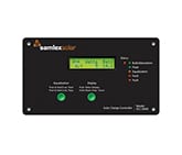
A solar home system consists of a solar charge controller, one or more solar modules, a battery and the connected loads. The solar charge controller is connected directly to the battery using as short a cable as possible, and fixed to the wall near to the battery, so that it can be effectively cooled by the passing air flow. In principle, the battery is always connected to the charge controller first. Then the solar module field is connected to the solar module input of the charge controller. Only direct current loads are used in solar home systems. They are connected directly to the load output of the charge controller. This means the Steca solar charge controllers always show the exact charge status of the battery, and thus ensure optimal battery maintenance in all situations. Various Steca energy-saving lights, Steca solar cooling units, DC-to-DC converters and other appliances can be used. The Steca solar charge controllers control the energy flow of the entire system. They make sure that the solar module charges the battery quickly and effectively, but they also protect the battery against overcharging. If the loads discharge the battery, the charge controller, thanks to its precision in calculating the charge status, switches off the load at exactly the right moment, thus protecting the battery from the dangers of deep discharge.
Furthermore, Steca charge controllers are equipped with an intelligent battery monitoring system. The most effective charging method is selected according to the requirements of the batteries. The charge controller is the central controlling component in solar home systems, since it affects all the functions of the system. For this reason, it is important to choose a reliable and efficient charge controller.
Figure 2: Intelligent battery monitoring system
You can also download this Application Note.
Solar home systems with Steca solar charge controllers
