What is the operation of standard-controllers in series and parallel connection?
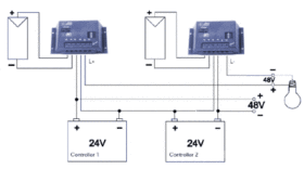
Figure 1: Series Connection
When controllers are connected in a series, neither the load output nor the module inputs are allowed to connect in a series, so that the controller is not damaged. When more systems are connected in a series, the total voltage can exceed the safety low voltage level. The single controller is not intended for use in this range and does therefore not correspond to the insulation requirements for DC-voltages higher than75V. When the controller is installed, pay attention that open-lying lines in which more than 50V are applied must be sufficiently insulated. The load disconnection can be used in 48V systems, Steca does however does not take any guarantee for this connection. In the worst case i. e. load disconnection at overvoltage, a voltage of 60V is applied on the FET of controller 2. As the max. admissabledra in-source can only be 55V, no advise for installation is given. As a rule, the load is disconnected because of overdischarge. Thus the FET cut-off voltage is smaller than 45V. When the FET is conducting, the voltage applied is smaller than1V.
Operation of standard controllers at high currents: Parallel Connection
In a parallel connection neither the load outputs nor the module inputs are allowed to be connected parallel, so that the controller is not damaged. As in single operation, all plus lines can be connected with each other and earthed.
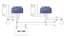
Figure 2: Parallel Connection
The load outputs must not be switched in parallel, as the controllers do not disconnect at the same time and thus the whole load current flows over the FET, which is still conducting. You can also download this Application Note.


